Sonar Basics
Sonar is a general term that refers to using sound waves for an application. Probably the most commonly recognized use is underwater target detection, such as in submarines: by transmitting sound waves away from a submarine and seeing how they bounce back, you can figure out if there is anything nearby you in the water. Sonar is also used for more detailed imaging of underwater targets, including shipwrecks and the ocean floor.
Similarly, underwater depth sounders use sonar: a boat’s depth sounder will send a sonar pulse straight down and by measuring how long it takes for the pulse to reflect back up to the boat’s hull, it can determine how deep the water is.
Lastly, sonar is used for underwater messaging. Above the water, sonar is used for some medical imaging applications.
The dry-land analogue to sonar is radar, which uses radio waves. These electromagnetic waves work well in the air, but not so much in the water. A sound wave is just molecules bouncing off of one another, so because water is much more dense than air, sonar works much better for underwater purposes.
Most often, sonar devices use very high frequencies: above the range that humans can hear (ultrasonic). Higher frequency sound waves give you more detailed imaging. The other benefit is that you can’t hear them.
The Project
I’ve spent a lot of time sailing and on boats, so a project involving sonar seemed very cool to me. Any time you’re coming into harbor on a boat, you need to keep an eye on the depth sounder to make sure you’re not going to run aground. It’s a relevant application of sonar that I used to use all the time, so I decided I wanted to build a sonar rangefinder to be able to measure distances.
The functionality
- A transmitter/speaker plays a short sonic pulse
- A receiver/microphone listens to detect the reflections of the pulse off of nearby objects
- A program determines the time elapsed between the original wave and the reflection. We know how fast sound travels in the air, so we can use this to determine how far the sound wave traveled from when it was output to when it was received.
I ended up deciding on two simplifications:
- Having to waterproof hardware is an unnecessary complication for an educational project, so I decided to use this device in the air.
- Lower frequencies: higher frequency waves need better hardware to be able to sample them properly, so it was cheaper and simpler for me to use sonic frequencies and hardware that I already had.
The Hardware
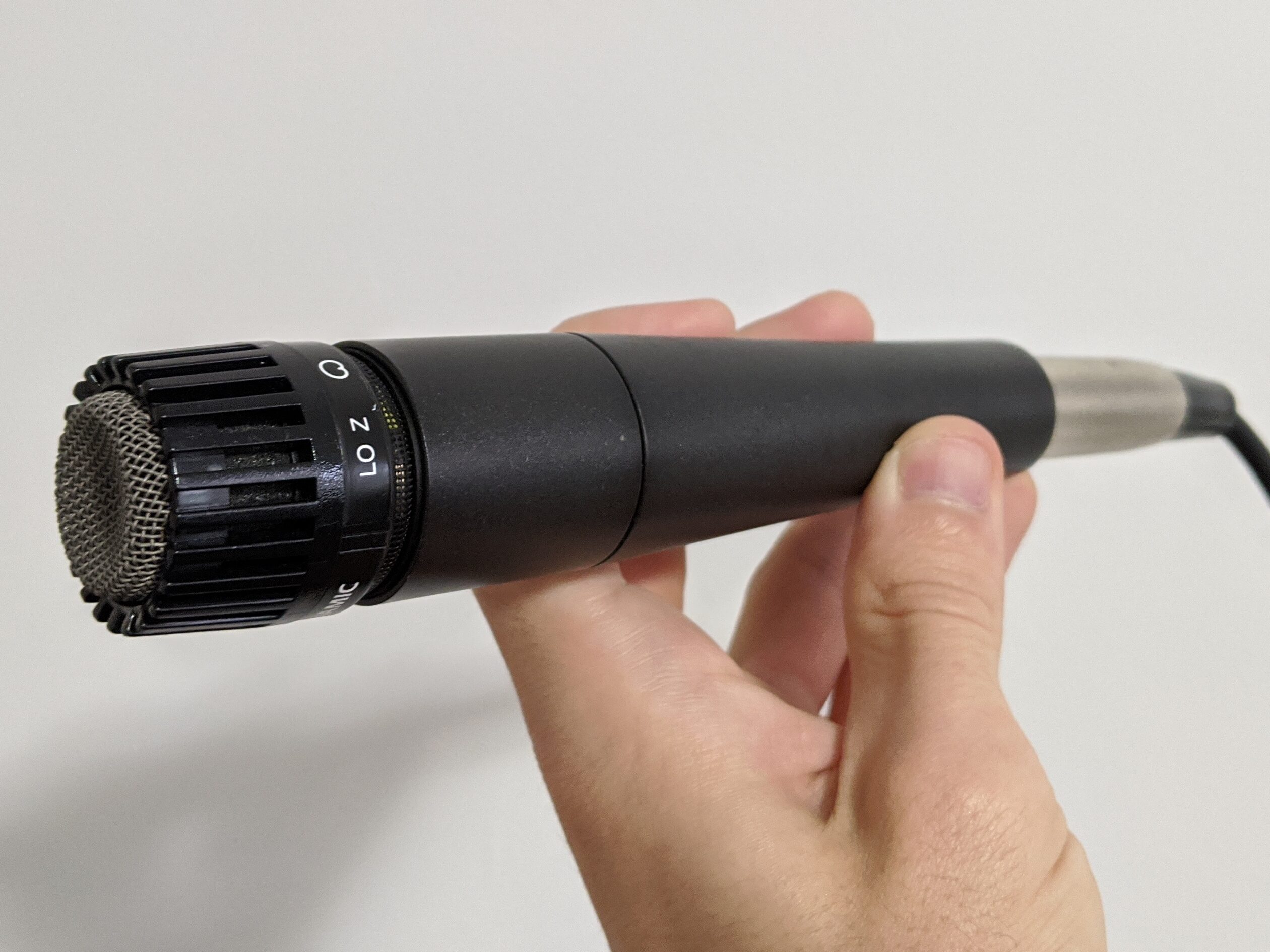
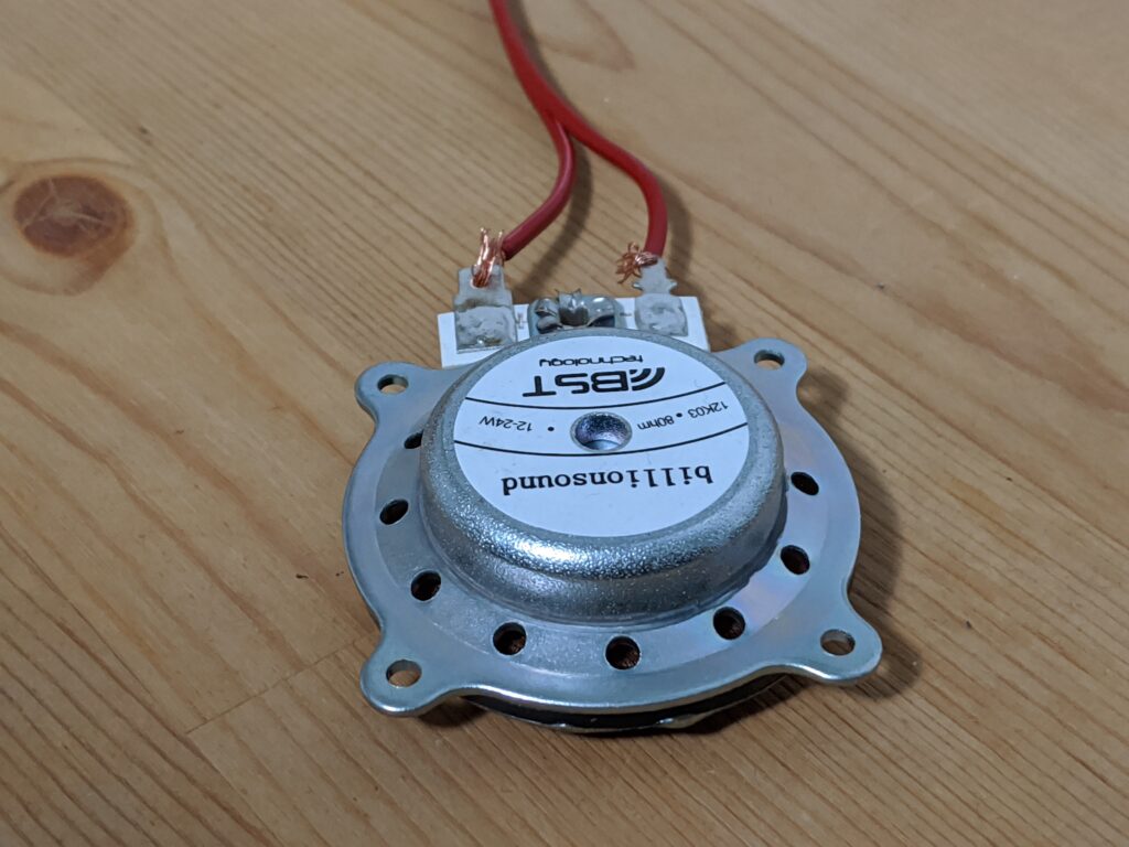
The transmitter/speaker: A little BillionSound speaker driver
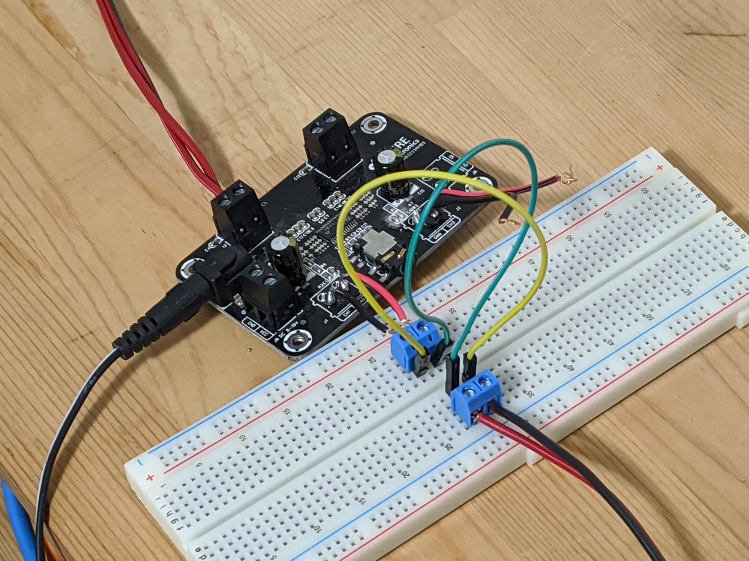
The amplifier: A Sure Electronics amplifier board
The receiver/microphone: An SM57
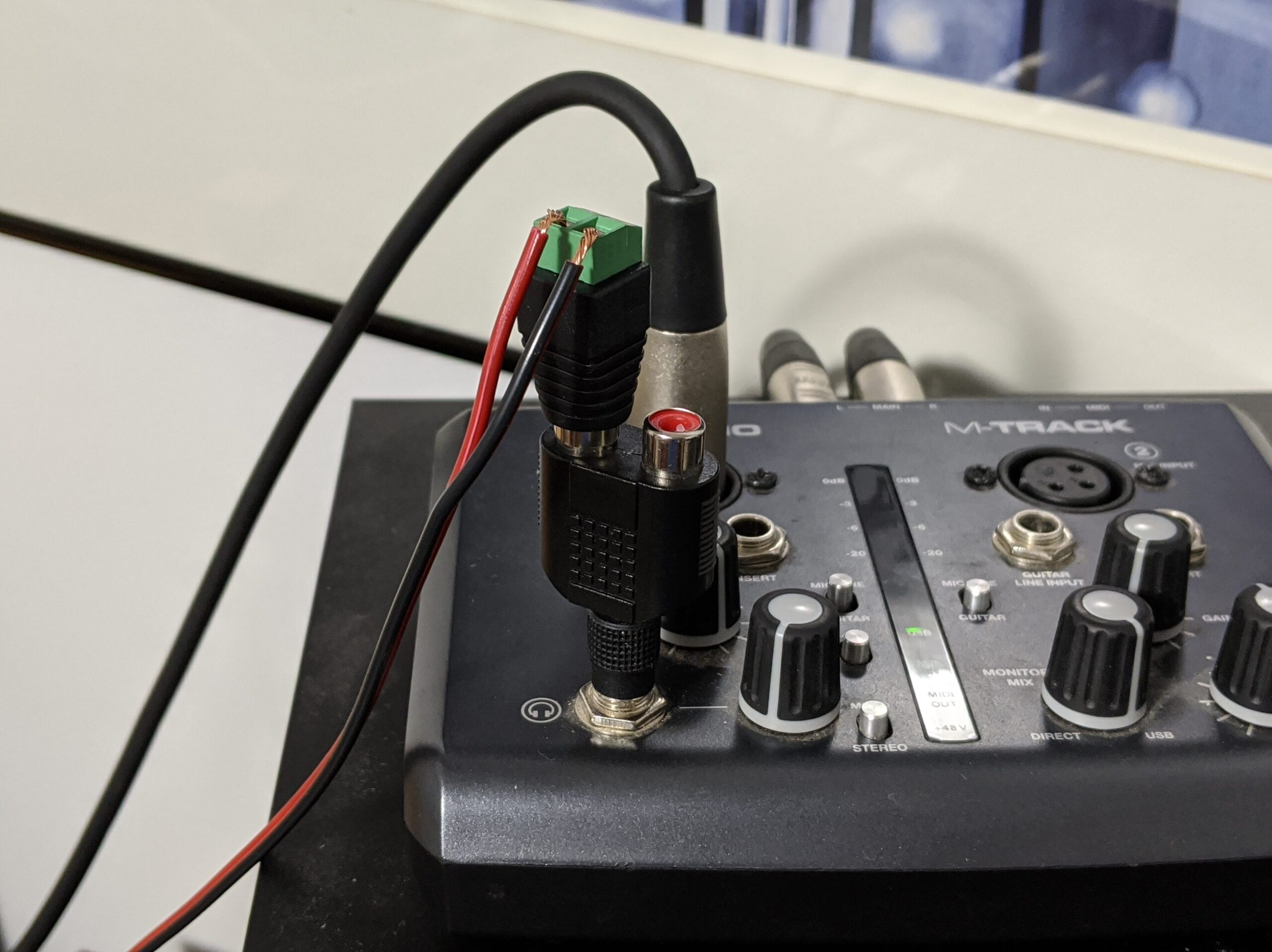
The interface: An M-Audio M-Track
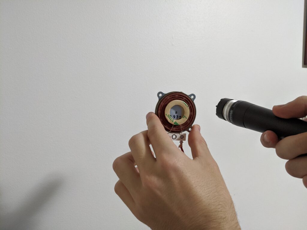
The microphone connected to my computer through the interface. The interface’s headphone out was converted from 1/4″ to 1/8″ to RCA to wire and connected to the amplifier, which connected to the speaker driver.
To use them, put the microphone and speaker right next to each other and point them at a large object (like the wall)
Signal Processing
Output Signal
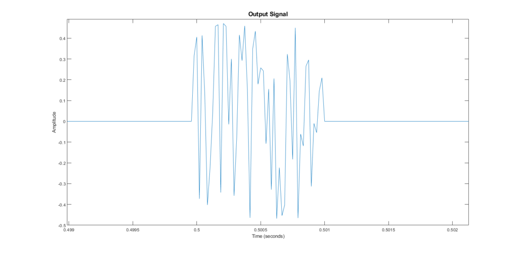
I generated 1/100 of a second of random noise to output through the driver. I chose noise because it was a loud, and my specific speaker could only play so loudly.
Input Signal
The example I will be using was with the microphone/speaker pointed at a wall, approximately 2 feet away from it. This is the raw input signal from the microphone:
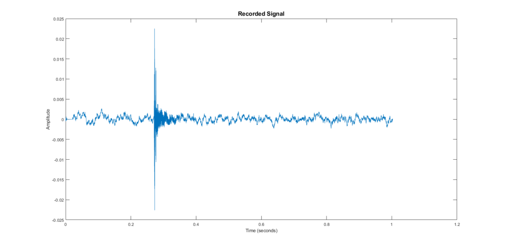
The raw input zoomed in on the important peaks:

RMS
So, how to process this? The first step is to take RMS values for this signal. RMS (root mean squared) is similar to an energy calculation, but you get one output value for several inputs. So to take the RMS of this signal, you’d have to choose how many samples you wanted to contribute to one RMS value.
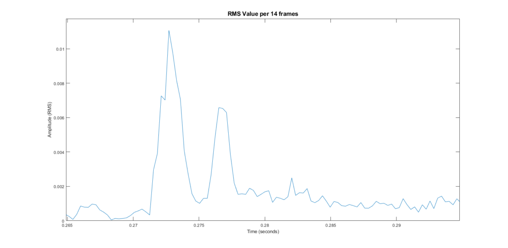
In my case, I chose the number of samples over which sound would travel 0.1m. Each RMS data point occurs every 0.1m, so my rangefinder has a resolution of 0.1m. The RMS signal:
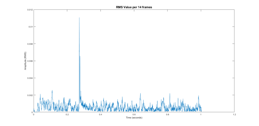
You can see that this is a much easier signal to process. Not only are all the peaks positive, there are much fewer of them!
Local Maxima
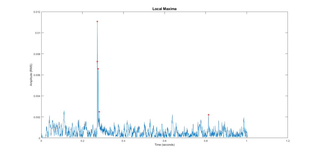
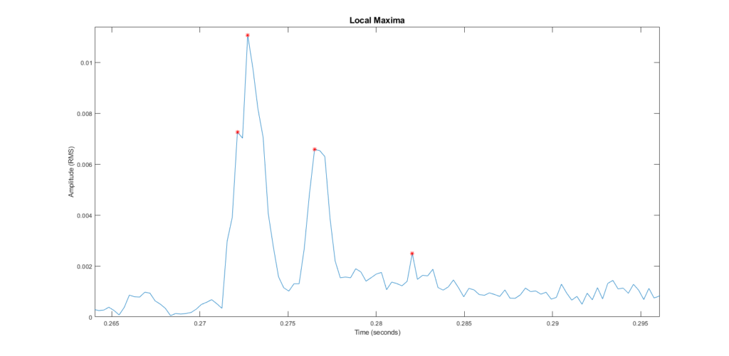
We can see that there are two clearly defined peaks here. The first is the original signal played by the speaker, and the second is the sound after it reflects off of the wall.
Using a slightly altered version of the local maxima function, I was able to pick points of interest on the graph:
Choosing Points
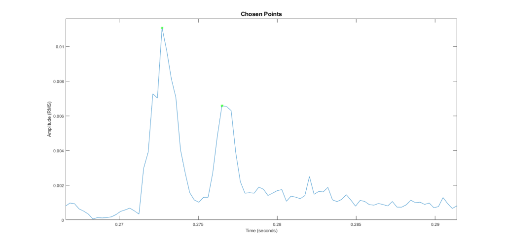
Now, the algorithm picks the highest point-of-interest it can find. Then it picks the highest point after the first chosen one. It’s a little hard to see, but they’re highlighted in green. These mark the original peak and the first reflection.
No Reflection
Let’s take a look at a signal in which the device was too far away from any object to pick up a reflection.
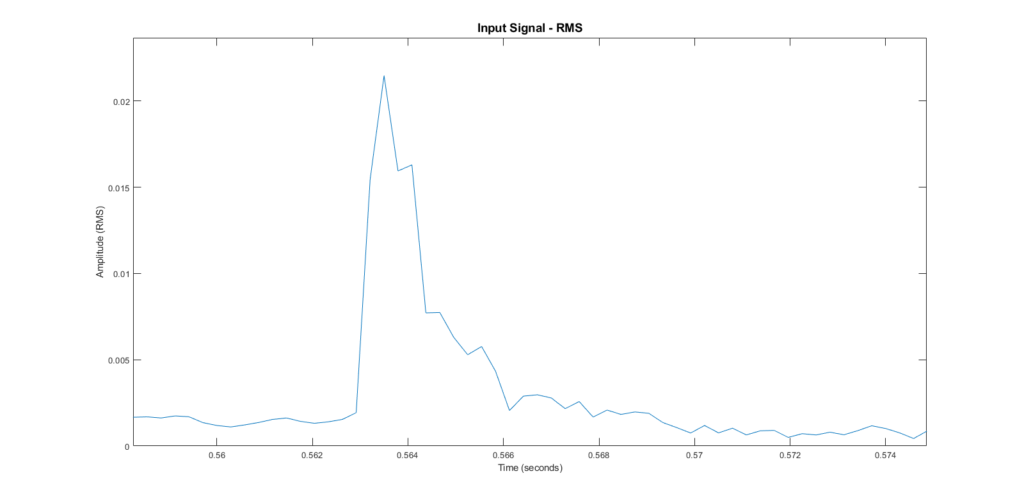
You can see, there’s only one peak from the original sound. There are no reflections. When we get the local maxima, you’ll see that some points are considered maxima that we shouldn’t consider as a second peak.
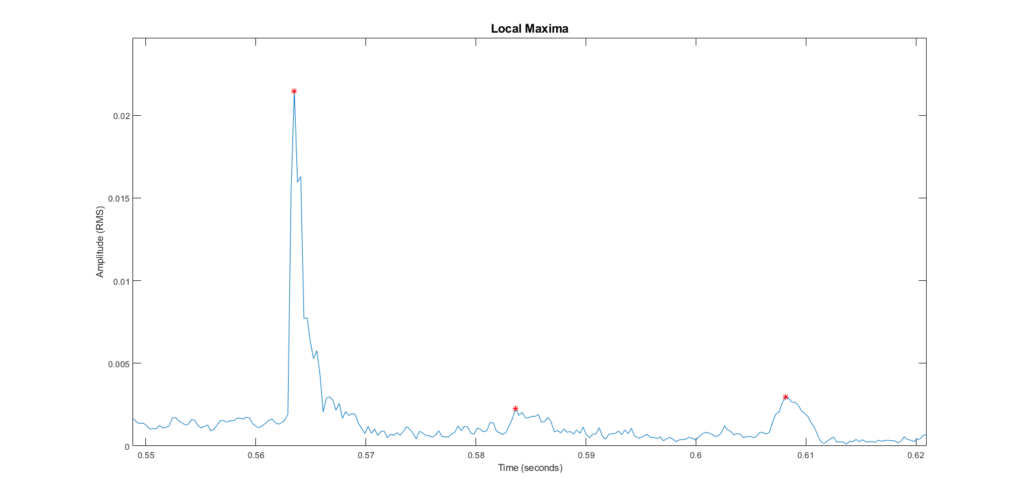
These maxima are just peaks of the noise in the room, so let’s see if we can deal with that background noise.
Background Noise
Before the program plays the output signal, it records a short period of silence. With this, it determines the highest amplitude of the background noise, and excludes any maxima chosen below that level.
Here’s the same example, this time excluding maxima below the noise floor:
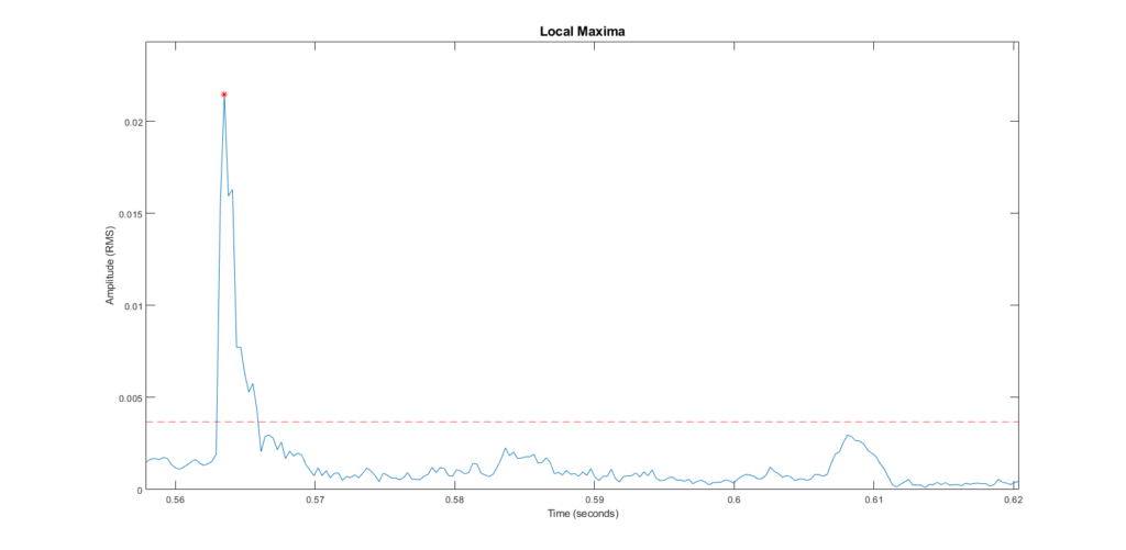
Much better. Now we appropriately only have one peak.
Here’s the original example with its noise floor line:
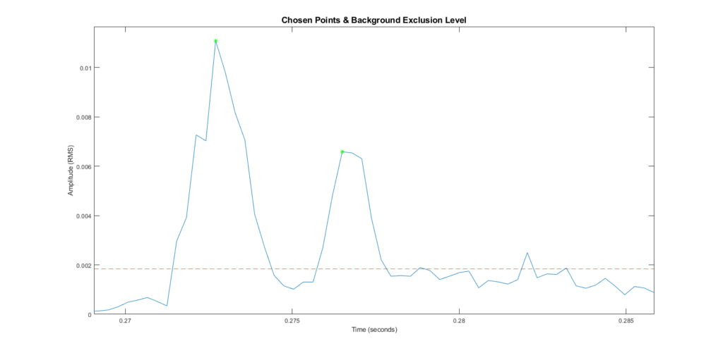
Calculating Distance
The rest of the algorithm is very simple. If only one point has been found, then no reflected wave was detected and the object is too far away for this rangefinder to detect. If there are two chosen points, then we can figure out the time between them, and use that to calculate how far the sound traveled.
Here’s the output for the original example. It’s decently accurate!

The Original Signal
In case you’re interested, here’s the original signal again. Remember, each RMS value is determined from several input values. Here, the samples corresponding to the two chosen RMS values have been highlighted.

Conclusion
The rangefinder works at a limited range and only when pointed at a large object such as a wall. It could only detect distances between around 1 and 3 feet. I think this is largely due to the volume I was getting from the speaker. With a more powerful output signal, it would be easier to detect the farther, quieter reflections.
Within these limited testing conditions, however, I have a product that works! And more importantly, I enjoyed the project and I learned a lot!